FW Tool features
The program is made of tabs, each solving its own task. Screenshots are from the English interface.
Firmware
Firmware file analysis, unpacking with a chosen nesting depth, an entropy map (shows compressed and encrypted areas) and rebuilding the package. The operation log can be copied or saved.
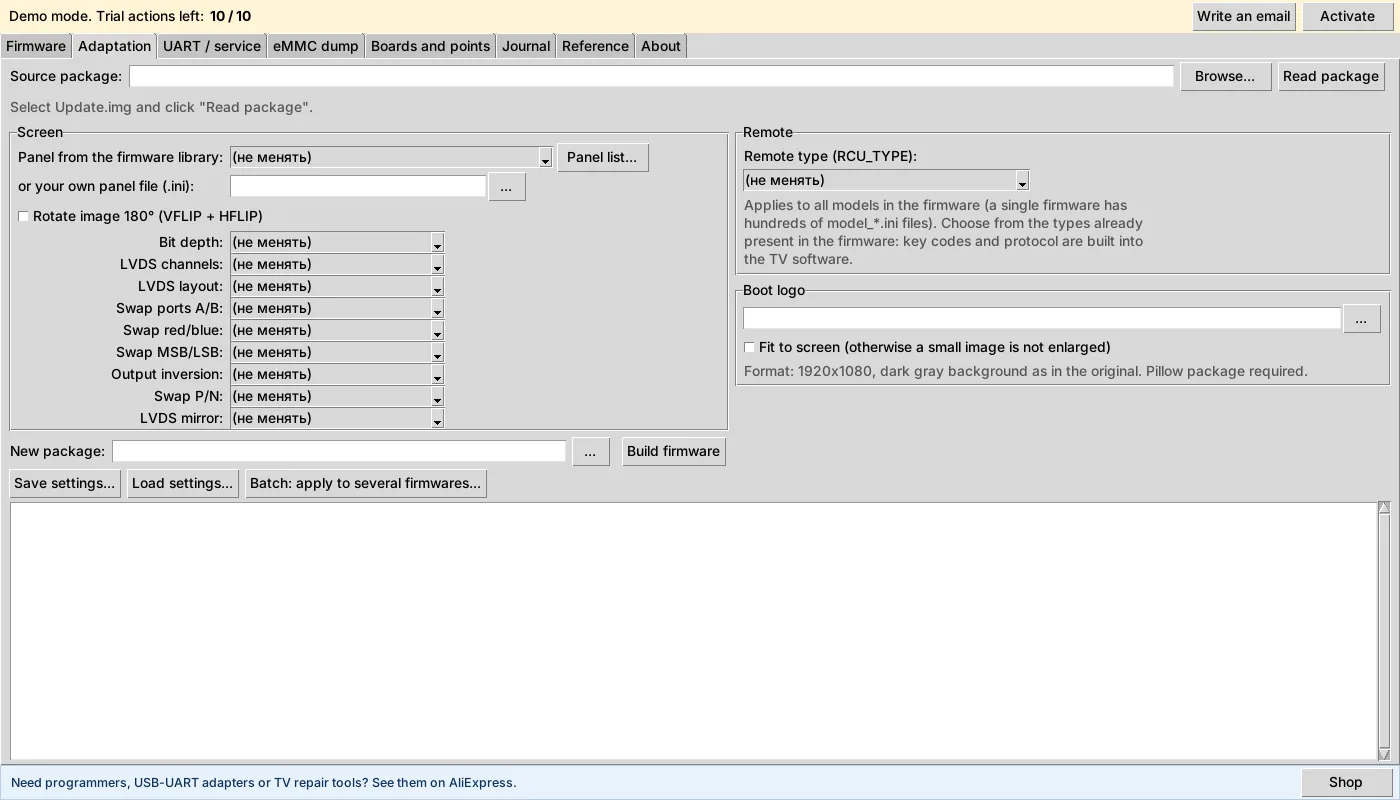
Adaptation
Reads a firmware package and lets you pick a panel from the library or your own .ini, set the remote type, bit depth, LVDS layout, swap ports A/B, red/blue, MSB/LSB, output inversion, mirroring and the boot logo. Settings can be saved and applied to several firmwares at once.
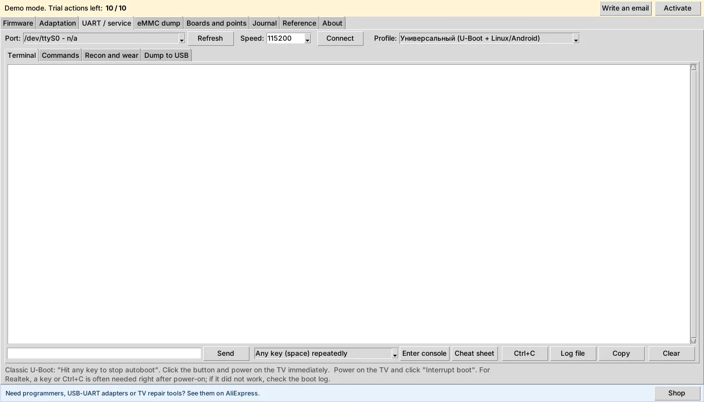
UART and service
A terminal with bootloader profiles, ready-made commands, “recon” (read-only: saves a report from which you can build a profile for your board), eMMC wear check from its registers and copying to USB.
eMMC dump
Analysis of a dump folder or a USER file, partition table, extraction of selected or all files, wiping, dump copy, adding the board to the database, eMMC analog finder by capacity and manufacturer, sending the record to the repair log. Writing to the dump is enabled by a separate checkbox; by default the dump is protected.
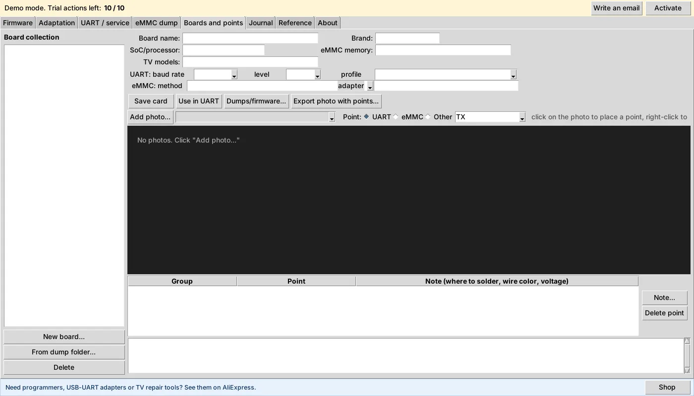
Boards and points
Your own board collection: photos, UART and eMMC connection points with notes (where to solder, wire colour, voltage) and UART parameters per board. Data stays on your computer.
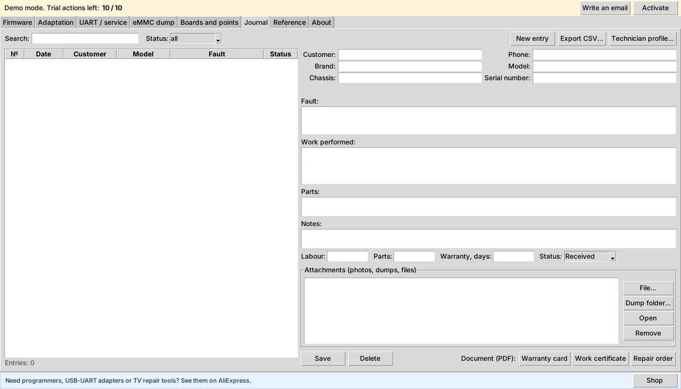
Repair log
Search and status filter, a repair card with the fault, work done, parts, warranty period and attachments (photos, dumps, files). It tells you when you have already repaired the same model. From the card you create a work order, a work certificate and a warranty card as PDF with your logo and details.
Reference
- Resistor colour code and E24 series, calculators (Ohm’s law, dividers, LEDs, backlight, capacitors).
- SMD codes and transistor substitutes, PWM controllers.
- SPI flash: IDs, sizes, packages, SOIC8/WSON8 pinout diagram.
- eMMC BGA153 ball map for in-circuit reading.
- Electrolytic ESR: typical values by capacitance and voltage, and evaluation of a measured value.
- Service menus, TV diagnostics, LVDS and panels, hex tools (dump compare, CRC32/MD5, search).
- A technician’s cheat sheet as a single printable PDF.
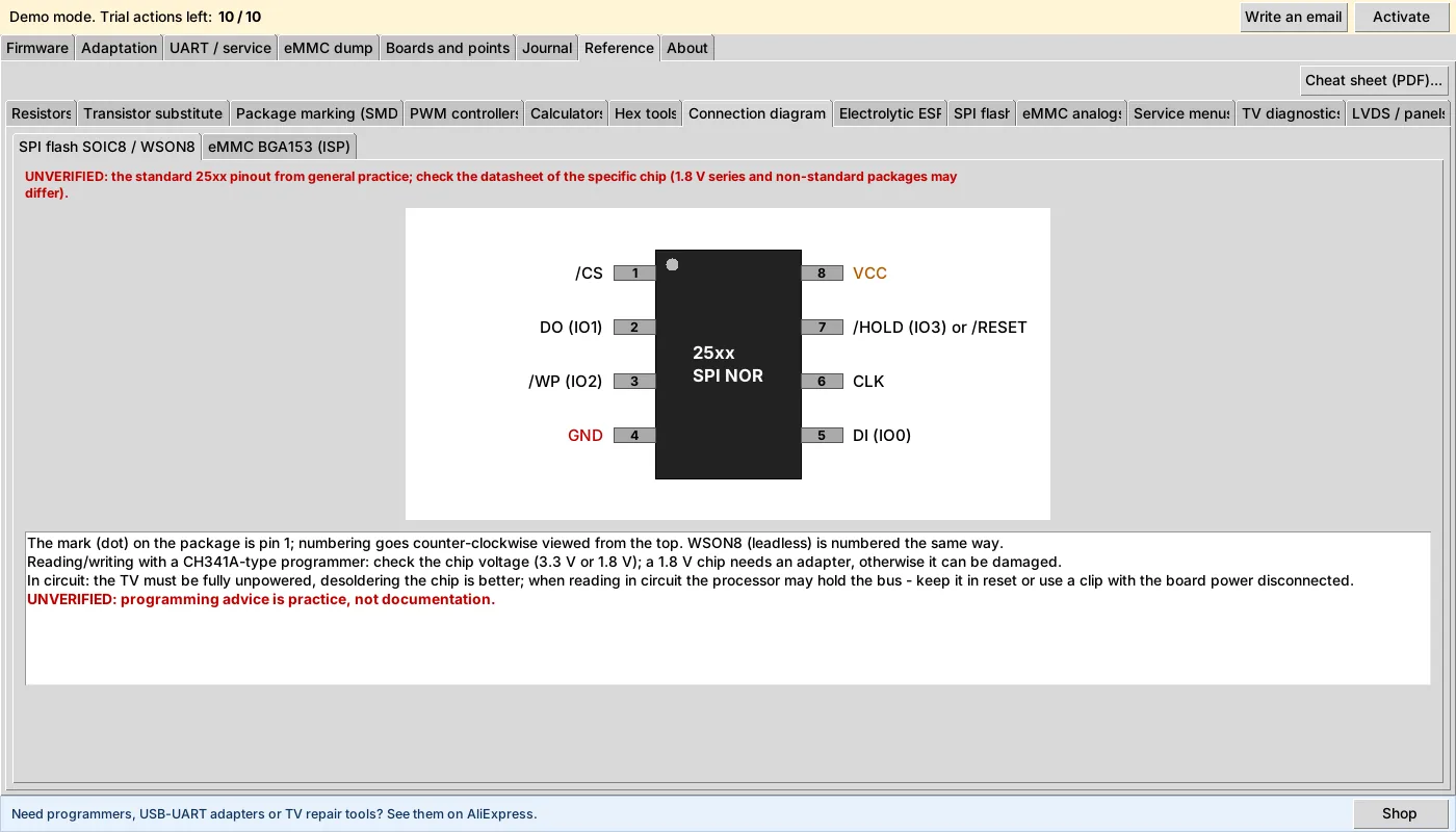
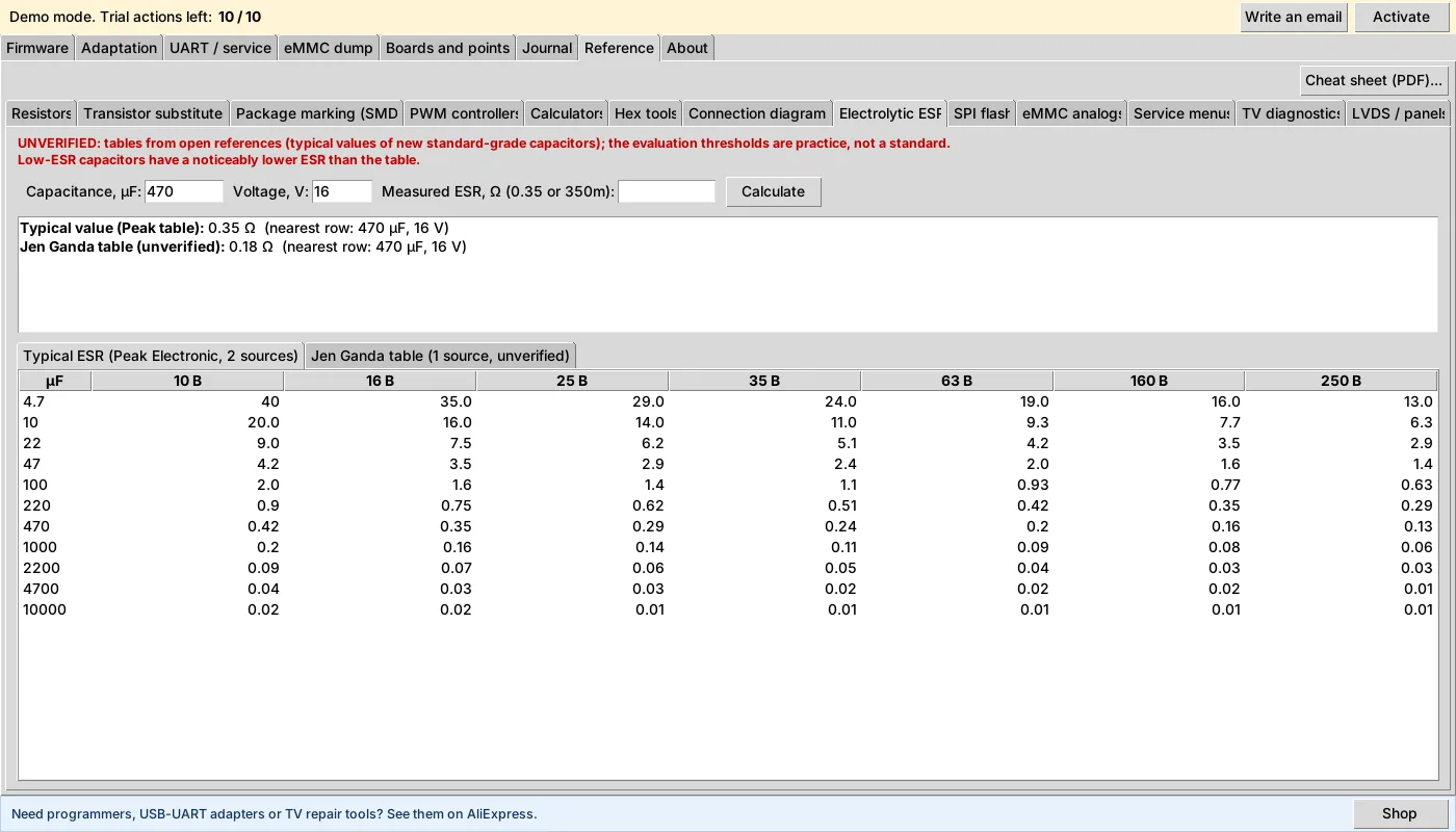
UNVERIFIED is the red mark the program uses for data not confirmed by two sources or a datasheet. We do not pass guesses off as facts.
Buy license